|
Exhaust Development
This page is going to be constantly updated over the next few
weeks, in my quest to design and manufacture an exhaust system specifically for my engine
tune.
As most people know, you can only go so far with porting then you come to big brick wall,
where by you cannot extract any more power from the engine.
The big power gains can be achieved by fine tuning the exhaust system. A couple of
millimetres to long or to short can have detrimental effects to the power curve, as does
only half a degree here or there on the expansion chambers.
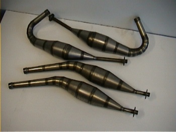
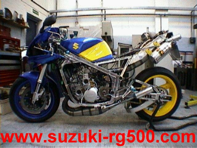
This was my first attempt at making a set of exhausts, not a complete disaster,
still made 108BHP but the power was coming to high up the rev range.
But this set of exhausts gave me a rough starting point as the basis for my new set. |
When designing an exhaust lots of factors come into play, Port timing, Peak RPM, Exhaust
port diameter, Horn coefficient and unsteady gas flow to name but a few.
First thing to do before we can go any further is to find out the exhaust gas temperature
at the belly section of the exhaust, this is achieved by using a thermal probe, inserted
into the belly of the exhaust to register exhaust gas temperature under normal riding
conditions.
Why do we need to know the Exhaust gas temperature?
We need to know the exhaust gas temperature because the exhaust tuned length relies on the
speed of sound for the scavenge pulse, where by the speed of sound changes accordingly
with exhaust gas temperature.
For example:-
| TEMPERATURE DegC |
TUNED LENGTH mm |
SPEED OF SOUND IN GAS m/s |
| 600 |
1005.7 |
592.25 |
| 550 |
976.4 |
575.04 |
As can be seen from the table, for approximately every DegC it
alters the tuned length by about 0.6mm, that may not sound like much but if you are 50
DegC wrong that makes a 30mm difference in tuned length.
The Exhaust gas temperature is taken mid-pipe to get an average temperature without
interference from combustion temperature.
The probe was inserted in the top pipes as well as the bottom pipes incase of temperature
variation between front and rear cylinders.
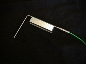
Thermal Probe |
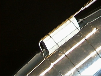
Probe inserted into belly section |
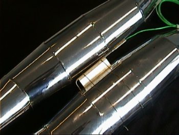
Exhausts ready for fitting |
As you can see the probes have been lock-wired around the exhaust,
as this is only a temporary arrangement. A 3mm diameter hole was drilled in the belly for
the probe to be inserted.
Now the probes are fitted, I can take the bike for a run to record maximum exhaust gas
temperature. ( Just have to wait for some dry weather )
Well I had a bit of a shock today I put the bike up on the dyno so
as to record exhaust gas temperature.
On my pipe data I usually work on the figure of 600deg for EGT but to my amazement, the
temperature in my pipes only reaches 440 deg on the rear cylinders and 430 degrees on the
front.
This difference in EGT equates to a staggering 96.0mm difference in tuned length, to my
previous pipes.
Now armed with this new information the manufacturing of the
exhausts can begin. First thing to do is to gather all the information of my engine
parameters, this can be seen below.
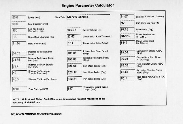
Then figures can be entered into the exhaust parameter calculator
as shown below.

Hopefully this should give us a very good pipe specification
(Notice I said hopefully)
Most parameters on the exhaust are hard and fast, the one grey area is to do with the horn
coefficient, this is mainly an educated guess on what value to use.
Now that we have the dimensions for the exhaust, the exhaust then needs to be developed on
the CAD system so that the piece parts can then be cut out on the laser machine.
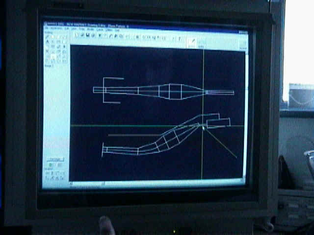
As can be seen from above, the route that the pipe has to take is
drawn on the computer to make sure that the pipe will fit the bike. The picture above
shows the route for the top pipes, the problem with the top pipe run is the stinger part
of the exhaust, there is not enough room on the bike to fit it in, to overcome this I have
decided to go for an internal stinger, this is where the stinger protrudes into the
divergent cone as well as protruding from the back.
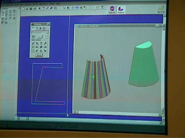
Now the pipe run is correctly routed, the cones then have to be
developed, this is done by means of 3D CAD software, which unfolds the cones to the
correct developed shape. (Easy when you have the correct tools!!)
From this information a tool path is then created to be downloaded to the laser machine to
be cut.
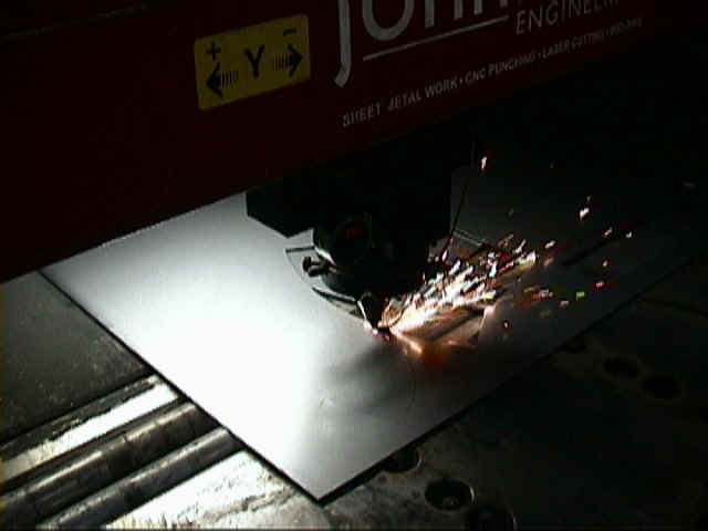
Once cut out you are left with the pieces as shown below.
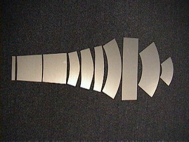
These pieces then need to be rolled to form the cones as below.

As well as the sheet parts there are also a couple of parts that
need to be machined
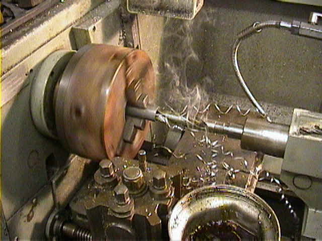
Stinger being machined |
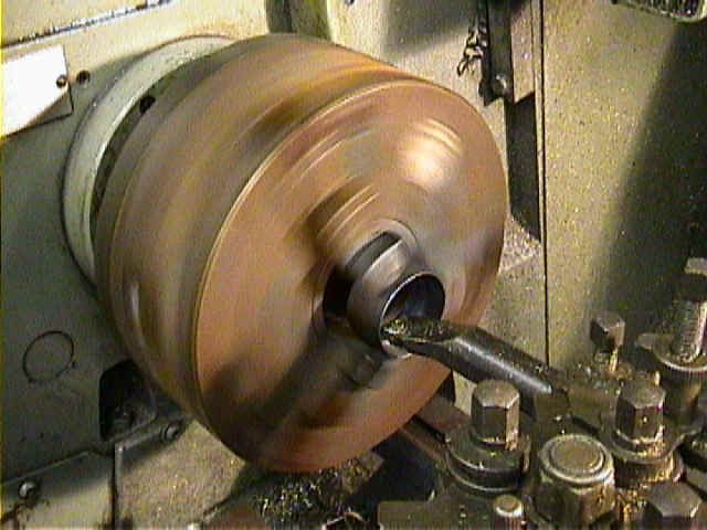
Exhaust flange being machined |
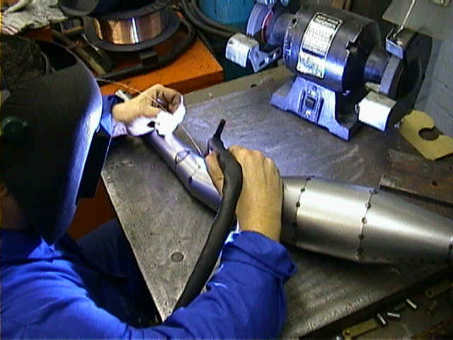
Once we have all the piece parts, the exhaust can then be welded
together.
And finally after welding, the exhausts can then be fitted to the
bike.
And there you have it, top pipes manufactured to fit my bike, now
I just have to do the same for the lower pipes.

I'm going to be running the new pipes on the dyno this week so I shall post the dyno
curves to this page in a week or so.
I've also made some adaptors to fit on the engine flange so I can alter the tuned length
of the pipe, just so I can have a play on the dyno to try a few different things.
Results

The green curve (Run 052) are Swarbrick exhausts.
The red curve (Run 078) are my first prototype exhausts.
The blue curve (Run 092) are my set of exhausts as detailed above.
Well there you have it 123.9 BHP @ 10400 RPM
64 FT/PNDS @10200 RPM
To be honest I didn't expect any more than 120 BHP due to the fact
I'm only running 31.5mm carbs.
In the next few weeks I'm going to be fitting a set of TMX35's, but have got to heavily
modify the inlet tracts to cope with the extra cross sectional area associated with the
TMX's.
Then hopefully I should see figures around the mid 130's.
| 
